FLUID MECHANICS LAB EQUIPMENTS
List of Equipments


EQUIPMENTS AVAILABLE IN COMPUTERIZATION ALSO
-
PIPE FITTINGS APPARATUS
-
FRICTION IN PIPES & PIPE FITTING COMBINED SET UP
-
IMPACT OF JET ON VANES
-
VENTURIMETER APPARATUS
-
ORIFICEMETER APPARATUS
-
FLOW NOZZLE APPARATUS
-
VENTURIMETER, ORIFICEMETER & FLOW NOZZLE COMBINED SET UP
-
NOTCH CALIBRATION APPARATUS
-
WEIRS CALIBRATION APPARATUS
-
NOTCH & WEIRS COMBINED SET UP
-
HYDRAULIC TILTING FLUME APPARATUS
-
VERTICAL ORIFICE & MOUTHPIECES APPARATUS
-
CALIBRATION OF COLLECTING TANK (GRAVIMETRIC METHOD)
-
DEAD WEIGHT PRESSURE GAUGE
-
BUOYANCY & METACENTRIC HEIGHT APPARATUS
-
BERNOULLI'S THEOREM APPARATUS
-
REYNOLDS APPARATUS
-
SINGLE STAGE CENTRIFUGAL PUMP TEST RIG
-
MULTI-STAGE CENTRIFUGAL PUMP TEST RIG
-
RECIPROCATING PUMP TEST RIG
-
PELTON WHEEL TURBINE TEST RIG
-
FRANCIS TURBINE TEST RIG
-
KAPLAN TURBINE TEST RIG
-
RECIPROCATING AIR COMPRESSOR TEST RIG
-
CENTRIFUGAL AIR BLOWER TEST RIG


Study of Head Loss: Measures frictional losses in straight pipes of varying diameters and materials.
Multiple Pipe Configurations: Includes a series of pipes with different internal diameters and surface conditions.
Manometer/Pressure Gauge Setup: Accurate differential pressure measurements across test sections.
Flow Control: Equipped with flow control valves to vary the discharge rate.
Clear Piping Layout: Transparent and color-coded piping (optional) for better visualization and learning.
Compact and Mobile: Bench-top design with sturdy frame, ideal for lab environments.
Technical Specifications
-
Pipe Materials: GI / Stainless Steel (customizable)
-
Pipe Diameters: Typically 13 mm, 19 mm, and 25 mm ID (custom configurations available)
-
Length of Pipes: Approximately 1.5 meters
-
Flow Measurement: Rotameter or volumetric tank with stopwatch
-
Pressure Measurement: U-tube manometers / digital differential pressure sensor
-
Pump: Self-priming centrifugal pump
-
Sump Tank Capacity: ~60 to 100 liters
-
Power Supply: 230 V AC, 50 Hz, single phase
Customized test set up also available

-
Study of Minor Losses: Quantifies head losses due to various pipe fittings under controlled flow conditions.
-
Multiple Fittings Included:
-
Elbow (90° and 45°)
-
Tee Junction
-
Sudden Expansion & Contraction
-
Gate Valve / Globe Valve
-
Bend and Reducer
-
-
Precision Pressure Measurement: U-tube manometers or digital pressure sensors for accurate differential readings.
-
Flow Control System: Valves provided to regulate and stabilize flow rate across different fittings.
-
Compact Bench-Top Setup: Ideal for laboratory demonstrations and student experiments.
Technical Specifications
-
Pipe Diameter: Typically 15 mm to 25 mm ID (custom sizes available)
-
Fitting Materials: PVC / GI / MS / SS (as required)
-
Pressure Measurement: U-tube manometers / digital manometers (optional)
-
Flow Measurement: Rotameter or volumetric tank with stopwatch
-
Water Circulation: Provided through a self-contained centrifugal pump
-
Sump Tank Capacity: ~80–100 liters
-
Power Supply: 230 V AC, 50 Hz, single phase
Customized test set up also available

-
Dual Experiment Capability: Study of major losses (Darcy-Weisbach) and minor losses (due to fittings) in one unit.
-
Multiple Pipe Diameters & Materials: Includes pipes of different sizes and finishes for frictional loss study.
-
Range of Fittings:
-
Sudden Expansion & Contraction
-
Elbows (90°/45°), Bends, Tees
-
Gate and Globe Valves
-
-
Accurate Measurement System:
-
Differential pressure using U-tube manometers or digital sensors
-
Flow rate via rotameter or volumetric method
-
Compact & Modular Design: Bench-mounted setup with labeled flow sections for ease of use.
-
Self-contained Water Circulation: Integrated pump and water storage tank for continuous operation
Technical Specifications
-
Pipe Diameters: 13 mm, 19 mm, 25 mm (customizable)
-
Pipe Materials: PVC, GI, Copper, or Stainless Steel
-
Fittings Included: Elbow, Bend, Sudden Expansion, Contraction, Valve, Tee, Reducer
-
Flow Measurement: Rotameter or measuring tank with stopwatch
-
Pressure Measurement: U-tube Manometers or Digital Pressure Sensors
-
Pump: Self-priming centrifugal pump (0.5 HP or as per design)
-
Sump Tank: ~40–60 liters capacity
-
Power Supply: 230V AC, 50Hz, single phase
Customized test set up also available

The Impact of Jet on Vanes Apparatus is an essential experimental setup in fluid mechanics used to study the force exerted by a fluid jet on different types of vanes. It helps students verify the principle of conservation of momentum and analyze how the shape and orientation of vanes affect the impact force. This apparatus is widely used in hydraulic laboratories for both teaching and research purposes.
Consist of
-
Interchangeable Vanes:
-
Flat Plate (Vertical/Inclined)
-
Hemispherical Vane
-
Curved Vane (Quarter-sphere)
-
Jet Nozzle with Flow Control: Adjustable nozzle for precise jet formation and direction.
-
Force Measurement System: load cell-based digital system.
-
Flow Control Valve: Regulates water flow rate to vary jet velocity.
-
Sturdy and Transparent Test Section: For easy observation of jet behavior.
Technical Specifications
-
Material of Vanes: Aluminum / Stainless Steel (non-corrosive)
-
Jet Diameter: Typically 6 mm to 10 mm
-
Vanes Types: Flat, hemispherical, and curved
-
Force Measurement: Digital (optional upgrade)
-
Flow Measurement: Rotameter
-
Water Circulation: Self-contained system with sump tank and centrifugal pump
-
Sump Capacity: 40–60 liters
-
Power Supply: 230 V AC, 50 Hz, single phase
Customized test set up also available

The Venturimeter Apparatus is designed to demonstrate the application of Bernoulli’s principle for flow measurement in a pipe. This apparatus helps in determining the discharge coefficient and verifying the theoretical relationship between pressure and velocity in a converging-diverging flow section. Widely used in educational and research labs, it’s an essential experiment in fluid mechanics.
Key Features
-
High-Precision Venturimeter: Made of durable material with a smooth converging and diverging section.
-
Differential Pressure Measurement: U-tube manometer or digital pressure sensor across inlet and throat.
-
Flow Control Mechanism: Gate valve provided for precise regulation of water flow.
-
Compact Bench-Top Unit: Easy to operate and designed for student use in labs.
-
Clear Flow Visibility: Optional transparent pipeline for visual understanding of flow behavior.
Technical Specifications
-
Venturimeter Material: Transparent Acrylic / Stainless Steel / Brass
-
Pipe Diameter: Inlet: 25 mm (typical), Throat: 12.5 mm (customizable)
-
Manometer: Mercury or water-based U-tube / Digital Pressure Sensor (optional)
-
Flow Measurement: Rotameter / Measuring Tank with Stopwatch
-
Pump: Centrifugal pump with suitable discharge head
-
Sump Tank Capacity: 80–100 liters
-
Power Supply: 230 V AC, 50 Hz, single phase
Customized test set up also available
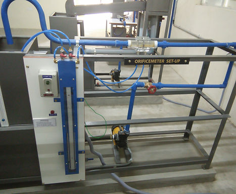
The Orificemeter Apparatus is designed to study the behavior of flow through an orifice and determine the coefficient of discharge (Cd) by applying Bernoulli’s principle. It is a key fluid mechanics experiment used to measure the flow rate in a pipeline by observing pressure drop across an orifice plate.
Key Features
-
Precision Orificemeter Assembly: Includes orifice plate fitted in a pipeline with upstream and downstream tapping points.
-
Pressure Measurement: U-tube manometer or optional digital pressure sensors to measure pressure differential.
-
Flow Control Valve: Provided to regulate flow and study its effect on pressure drop.
-
Flow Measurement: Rotameter or volumetric tank with stopwatch for accurate discharge measurement.
-
Compact Design: Bench-top setup with user-friendly layout for student experiments.
-
Durable Construction: Stainless steel or PVC piping and fittings ensure long-term reliability.
Technical Specifications
-
Orifice Plate Material: Stainless Steel /Acrylic
-
Pipe Diameter: Inlet typically 25 mm, with orifice diameter customizable (e.g., 12.5 mm)
-
Pressure Measurement: U-tube Manometer (Mercury/Water) or Digital Sensors
-
Flow Measurement: Rotameter or volumetric tank
-
Pump: Self-priming centrifugal pump, ~0.5 HP
-
Sump Tank: ~80–100 liters
-
Power Supply: 230 V AC, 50 Hz, single phase
Customized test set up also available

The Flow Nozzle Apparatus is a fluid mechanics experimental setup used to determine the flow rate of incompressible fluids through a converging nozzle section. It is based on Bernoulli’s theorem and helps evaluate the coefficient of discharge (Cd) for a nozzle. This apparatus is commonly used in academic and research labs to study pressure variation, velocity change, and flow characteristics through a nozzle.
Key Features
-
Standard Flow Nozzle: Smoothly machined converging nozzle installed between two pressure tapping points.
-
Pressure Differential Measurement: U-tube manometers or optional digital pressure sensors.
-
Flow Control Valve: For regulating flow and studying the effect on pressure drop and velocity.
-
Compact Bench-Mounted Design: Easy to install and operate in laboratory environments.
-
Transparent or Opaque Pipeline: Available as per requirement for visibility or durability.
Technical Specifications
-
Nozzle Material: Brass / Stainless Steel / Acrylic
-
Pipe Diameter: Inlet – 25 mm (customizable), Nozzle Throat – typically 12.5 mm
-
Pressure Measurement: U-tube manometers or digital pressure gauges
-
Flow Measurement: Rotameter or volumetric tank with stopwatch
-
Pump: Centrifugal pump (~0.5 HP) for closed-loop water circulation
-
Sump Tank: 80–100 liters
-
Power Supply: 230 V AC, 50 Hz, single phase
Customized test set up also available

The Combined Flow Measuring Devices Setup is a versatile, multi-functional apparatus designed to study and compare three standard flow measurement devices: Venturimeter, Orificemeter, and Flow Nozzle — all integrated into a single compact unit. It enables students to analyze the principles of Bernoulli’s theorem, determine the coefficient of discharge (Cd) for each device, and compare their accuracy, pressure losses, and flow behavior under identical conditions.
This setup is an efficient, space-saving solution for fluid mechanics labs in engineering colleges, technical institutes, and research facilities.
Key Features
-
Three Flow Devices in One Setup:
-
Venturimeter (converging-diverging type)
-
Orificemeter (standard orifice plate)
-
Flow Nozzle (streamlined converging nozzle)
-
-
Common Water Supply & Pump System
-
Differential Pressure Measurement:
-
U-tube manometers for each device
-
Optional: Digital pressure sensors
-
-
Flow Control Valve: Adjust and regulate flow rate
-
Flow Measurement: Rotameter or volumetric tank with stopwatch
-
Compact & Modular Layout: Clearly labeled sections with selector valves to switch between devices
Technical Specifications
-
Material: PVC / Acrylic / SS (as required)
-
Pipe Diameter: 25 mm inlet (typical); throat/orifice customizable
-
Flow Devices: Interchangeable or inline-mounted
-
Pressure Tapping Points: At inlet and throat for all devices
-
Flow Rate Measurement: Rotameter or measuring tank (20–40 liters)
-
Pump: Centrifugal (0.5 HP), single phase
-
Sump Tank: ~80 - 100 liters
-
Power Supply: 230 V AC, 50 Hz
Customized test set up also available

The Notch Apparatus is a fundamental experimental setup used to determine the discharge over different types of notches such as rectangular, triangular (V-notch), and trapezoidal notches. It demonstrates open channel flow characteristics and helps students understand flow measurement techniques in weir-type structures. The setup is ideal for validating theoretical discharge equations and calculating the coefficient of discharge (Cd) for each notch profile.
This apparatus is essential for Fluid Mechanics and Hydraulic Engineering laboratories in academic and technical institutions.
Key Features
-
Interchangeable Notch Plates:
-
Rectangular notch
-
60° / 90° V-notch (triangular)
-
Trapezoidal notch
-
-
Stainless Steel / Acrylic Notch Tank: Corrosion-resistant and durable
-
Collecting Tank with Measuring Scale: For accurate volume and time measurements
-
Hook/Point Gauge: Provided for precise head measurement above the notch
-
Compact and Transparent Layout: Easy to observe and operate during experiments
-
Self-contained Circulating System: Closed-loop water supply with sump and pump
Technical Specifications
-
Material of Notch Plates: Stainless Steel
-
Types of Notches: Rectangular, 60° V-notch, Trapezoidal (customizable)
-
Measuring Tank: Graduated, with a scale and stopwatch for discharge calculation
-
Hook/Point Gauge Range: 0–300 mm (least count 0.1 mm)
-
Pump: Centrifugal, ~1.0 HP
-
Sump Capacity: 100–120 liters
-
Power Supply: 230 V AC, 50 Hz, single phase
Customized test set up also available

The Weirs Calibration Apparatus is designed to study and calibrate the discharge characteristics of various types of weirs used in open channel flow measurement. The apparatus allows students to determine the coefficient of discharge (Cd) and validate theoretical discharge equations by conducting controlled experiments under laboratory conditions. It’s an essential tool for civil and hydraulic engineering laboratories focused on water resource studies.
Key Features
-
Multiple Interchangeable Weir Plates:
-
Rectangular Weir
-
V-notch Weir (60° / 90°)
-
Trapezoidal / Cipolletti Weir
-
-
Transparent Flow Channel: Enables clear observation of flow over the weir
-
Precise Head Measurement: Using a point gauge or hook gauge over the crest
-
Measuring Tank with Scale: For volumetric discharge calculation using stopwatch
-
Closed-loop Circulation System: Self-contained pump and sump ensure continuous water supply
-
Compact Bench-Top Design: Ideal for academic lab setups
Technical Specifications
-
Weir Plate Material: Stainless Steel / Acrylic
-
Types of Weirs: Rectangular, V-notch (60°, 90°), Trapezoidal (as per requirement)
-
Flow Channel Dimensions: Typically 600–900 mm length × 200 mm width × 300 mm height
-
Head Measurement: Hook/point gauge with 0.1 mm least count
-
Flow Measurement: Volumetric method (graduated tank + stopwatch) or rotameter
-
Pump: Centrifugal (~1.0 HP), 230 V AC
-
Sump Capacity: 100–120 liters
-
Power Supply: 230 V AC, 50 Hz, single phase
Customized test set up also available
The Notch & Weir Combined Setup is a versatile experimental apparatus that integrates both notch and weir flow measurement in a single, compact system. This combined unit enables students and researchers to study open channel flow characteristics and determine the coefficient of discharge (Cd) for various types of notches and weirs under controlled conditions. It provides hands-on understanding of flow behavior, energy loss, and discharge relationships — essential for fluid mechanics and hydraulic engineering education.
Key Features
-
Interchangeable Flow Measurement Plates:
-
Rectangular Notch
-
V-Notch (60°, 90°)
-
Trapezoidal Notch
-
Rectangular Weir
-
Cipolletti / V-Notch Weir (optional)
-
-
Transparent Flow Section: Provides clear visualization of flow over notch/weir
-
Precise Head Measurement: Using a point or hook gauge with fine resolution
-
Graduated Collecting Tank: Allows volumetric discharge measurement via stopwatch
-
Compact & Bench-Top Friendly: Ideal for space-saving lab installations
-
Closed-Loop Water System: With integrated sump tank and recirculation pump
Technical Specifications
-
Plate Material: Stainless Steel / Acrylic
-
Channel Dimensions: ~600–900 mm length × 200 mm width × 300 mm height
-
Measurement System:
-
Head: Hook or Point Gauge (0.1 mm resolution)
-
Discharge: Graduated tank + Stopwatch or optional Rotameter
-
-
Pump: Centrifugal, ~1.0 HP, Single Phase
-
Sump Tank: 100–120 liters (non-corrosive material)
-
Power Supply: 230 V AC, 50 Hz, single phase
Customized test set up also available

The Hydraulic Tilting Flume is a precision-engineered open channel flow apparatus used to study and demonstrate fundamental hydraulic phenomena such as flow over weirs, hydraulic jumps, critical/subcritical flow, energy dissipation, sediment transport, and sluice gate behavior. The flume can be inclined to simulate varying channel slopes, making it highly effective for both teaching and research in fluid mechanics and open channel hydraulics.
This advanced apparatus is widely used in civil engineering, hydraulic engineering, and water resources laboratories.
Key Features
-
Tiltable Channel: Adjustable slope using screw jack or geared tilting mechanism
-
Transparent Flow Section: Toughened glass or clear acrylic sidewalls for full flow visibility
-
Flow Straightener & Calming Section: Ensures uniform flow profile at the inlet
-
Interchangeable Flow Models:
-
Broad/Sharp-Crested Weirs
-
Sluice Gates
-
Spillways
-
Hydraulic Jump Blocks
-
-
Precise Water Supply Control: With regulating valve and flow measurement unit
-
Digital or Hook Gauge: For accurate water level/head measurement
Technical Specifications
-
Channel Length: 2.5 m / 5 m / 7.5 m (customizable)
-
Channel Width: 150 mm to 300 mm (as required)
-
Side Walls: Transparent Acrylic / Glass
-
Tilting Mechanism: Manual screw jack or motorized option
-
Slope Range: -2% to +5% (adjustable)
-
Discharge Measurement: Rotameter or volumetric tank with stopwatch
-
Pump: Centrifugal (1 HP or higher depending on flume size)
-
Sump Tank Capacity: 100–200 liters (as per design)
-
Power Supply: 230 V AC, 50 Hz
Customized test set up also available

The Vertical Orifice & Mouthpieces Apparatus is an essential fluid mechanics lab setup used to study and compare the discharge and jet trajectory of water through a vertical orifice and various mouthpieces. It allows students to determine the coefficient of discharge (Cd), coefficient of velocity (Cv), and coefficient of contraction (Cc) through experimental analysis. This apparatus offers valuable insight into jet formation, energy loss, and fluid flow through small openings.
It is ideal for hydraulic and fluid mechanics laboratories in engineering colleges, technical institutes, and research centers.
Key Features
-
Interchangeable Orifice & Mouthpiece Attachments:
-
Short cylindrical mouthpiece
-
Convergent mouthpiece
-
Borda’s mouthpiece
-
Standard sharp-edged vertical orifice
-
Transparent Water Tank: Allows full observation of jet formation and flow behavior
-
Jet Trajectory Measurement Panel: With grid markings to study the parabola of the emerging jet
-
Head Scale / Hook Gauge: For accurate measurement of water head above the orifice
-
Graduated Measuring Tank: For precise discharge calculation using stopwatch method
Technical Specifications
-
Orifice Diameter: 6–12 mm (as required)
-
Tank Material: Transparent Acrylic or SS with clear front face
-
Mouthpiece Materials: Brass / SS (machined to precise dimensions)
-
Measurement Tank: 30–40 liters with scale
-
Jet Trajectory Plate: Calibrated for height and range analysis
-
Pump: Centrifugal (1.0 HP), single phase
-
Sump Capacity: 100–120 liters
-
Power Supply: 230 V AC, 50 Hz
Customized test set up also available

The Calibration of Collecting Tank using the Gravimetric Method apparatus is used to accurately calibrate a volumetric tank by comparing the volume of water collected with its corresponding mass, using a weighing scale. This method is based on the fundamental relation between mass, volume, and density, making it highly precise for establishing tank calibration curves.
This experiment is crucial for ensuring accurate flow rate measurements in hydraulic labs and is typically used before experiments like Venturimeter, Orificemeter, and Notch Discharge studies.
Key Features
-
Stainless Steel or Acrylic Collecting Tank: With clear graduation markings
-
Digital or Mechanical Weighing Scale: High-precision balance to measure mass of water collected
-
Adjustable Inlet Valve: For regulating water flow during calibration
-
Graduated Scale Plate: For preliminary volume marking
-
Drain Valve: Provided for easy emptying of tank after each trial
-
Compact and Modular: Suitable for all standard fluid mechanics labs
Technical Specifications
-
Tank Volume: Typically 20–50 liters
-
Graduation Scale: Marked in liters or milliliters
-
Weighing Scale Capacity: 50–100 kg (least count 10–100 g)
-
Tank Material: SS
-
Inlet Control: Manual valve or tap
-
Drain Valve: Quick-action ball valve
-
Support Frame: Powder-coated MS stand with leveling feet
Customized test set up also available

The Dead Weight Pressure Gauge Tester is a precision calibration apparatus used to verify and calibrate pressure gauges using known applied weights over a piston-cylinder system. This device generates a highly accurate pressure reference based on fundamental physical principles and is widely regarded as a primary standard in pressure measurement.
Ideal for calibration labs, instrumentation training centers, and fluid mechanics laboratories, this apparatus provides hands-on experience in pressure measurement, calibration methods, and error analysis.
Key Features
-
Precision-Machined Piston & Cylinder Assembly: Ensures minimal friction and high sensitivity
-
Dead Weights Set: Calibrated weights marked in kg or Newtons, traceable to national standards
-
Pressure Generation System:
-
Screw pump or plunger for manual pressurization
-
Oil reservoir for hydraulic pressure transmission
-
Gauge Mounting Platform: For connecting and testing pressure gauges (Bourdon, digital, etc.)
-
Compact, Rigid Base Structure: With anti-vibration leveling supports
Technical Specifications
-
Pressure Range: 0 to 10 kg/cm² / 0–25 kg/cm² / 0–70 kg/cm² (customizable)
-
Weights Set: Calibrated steel or brass weights
-
Piston Diameter: Typically 10–20 mm depending on pressure range
-
Gauge Port Size: 3/8” or 1/2” BSP/NPT threads
-
Working Fluid: Oil (standard)
-
Accuracy: ±0.1% of full scale or better
-
Base Material: MS powder-coated frame
Customized test set up also available

The Buoyancy & Metacentric Height Apparatus is an essential experimental setup used to determine the center of buoyancy, metacentric height, and stability of floating bodies. It helps students understand hydrostatic principles, such as Archimedes’ principle, and analyze conditions under which a floating body remains in stable, neutral, or unstable equilibrium.
This apparatus is widely used in fluid mechanics, naval architecture, and marine engineering labs for foundational learning of floating body dynamics.
Key Features
-
Floating Body Model: A rectangular or cylindrical pontoon-type vessel with adjustable ballast
-
Adjustable Weight Arm: Sliding weight on a horizontal scale for tilting and stability study
-
Graduated Tilting Scale & Pointer: Measures tilt angle accurately
-
Transparent Water Tank: Allows clear observation of buoyancy effects
-
Leveling Legs: Ensures accurate alignment and setup
-
Robust Construction: Rust-proof, corrosion-resistant materials for long-term lab use
Technical Specifications
-
Floating Body Material: Stainless Steel / Acrylic (non-corrosive)
-
Water Tank Dimensions: ~600 mm × 400 mm × 400 mm (customizable)
-
Movable Weight: Typically 100–500 grams, sliding along graduated arm
-
Angle Measurement: ±30° with protractor or pointer scale
-
Tank Material: Stainless steel
-
Overall Frame: MS Powder Coated / Aluminum with leveling knobs
Customized test set up also available

The Bernoulli’s Theorem Apparatus is a fundamental experimental setup used to demonstrate and verify Bernoulli’s equation along a streamlined flow. The apparatus allows students to observe how pressure, velocity, and elevation interact in a converging-diverging duct, validating the principle of conservation of energy in fluid dynamics.
This setup is essential for fluid mechanics laboratories in engineering colleges, polytechnic institutes, and training centers.
Key Features
-
Transparent Converging-Diverging Duct: Acrylic flow channel for full visibility of streamlines
-
Multiple Pressure Tapping Points: Along the length of the duct to measure static head
-
Manometer Bank: Multi-tube water or mercury manometer for clear pressure difference observation
-
Water Circulation System: Closed-loop with centrifugal pump and sump tank
-
Flow Control Valve: Regulates flow rate for dynamic analysis
-
Compact and Educational Design: Ideal for group demonstrations and lab assignments
Technical Specifications
-
Material: Transparent Acrylic / Polycarbonate duct
-
Duct Profile: Converging-Diverging, typically 25 mm inlet diameter
-
Number of Pressure Points: 6 to 9 tapping points
-
Manometer: Multi-tube U-tube with scale (water or mercury based)
-
Flow Regulation: By control valve and optional rotameter
-
Pump: Centrifugal, ~0.5 HP
-
Sump Tank Capacity: 50–60 liters
-
Power Supply: 230 V AC, 50 Hz, single phase
Customized test set up also available

The Reynolds Apparatus is a classic experimental setup used to demonstrate laminar, transitional, and turbulent flow in a pipe. It allows students to visualize the nature of fluid flow and calculate the Reynolds number, a key dimensionless parameter in fluid mechanics that determines the flow regime. A dye injector enables easy observation of fluid streamlines under varying flow rates.
Key Features
-
Transparent Flow Tube: Long acrylic or glass pipe to clearly observe fluid motion
-
Dye Injection System: With fine nozzle for introducing dye streamlines
-
Water Reservoir and Pump: Provides constant head and controlled flow
-
Flow Control Valve: To vary and maintain different flow regimes
-
Graduated Measuring Tank: For volumetric flow rate calculation
-
Compact and Bench-Top Friendly Design
Technical Specifications
-
Tube Material: Transparent Acrylic or Borosilicate Glass
-
Tube Diameter: 10–20 mm (typical)
-
Tube Length: ~1000–1200 mm
-
Dye Reservoir: With adjustable drip mechanism
-
Flow Measurement: Volumetric tank (20–30 liters) + stopwatch
-
Pump: Centrifugal, 0.5 HP
-
Sump Tank Capacity: 50–60 liters
-
Power Supply: 230 V AC, 50 Hz, single phase
Customized test set up also available

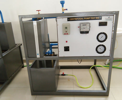
The Single Stage Centrifugal Pump Test Rig is a comprehensive experimental setup designed to evaluate the performance characteristics of a centrifugal pump under various flow conditions. It enables students to measure parameters such as discharge, head, input/output power, and overall efficiency, and to draw the characteristic curves (H-Q, P-Q, η-Q). The rig is ideal for understanding the working and energy conversion principles of dynamic pumps.
Widely used in fluid mechanics and hydraulic machinery laboratories, this test rig is essential for academic training and industrial skill development.
Key Features
-
Single Stage Centrifugal Pump: Standard industrial-type pump with clear specifications
-
Dynamometer or Energy Meter: Measures input power (electrical or mechanical)
-
Suction & Delivery Pressure Gauges: Analog or digital options available
-
Flow Measurement: Rotameter or measuring tank with stopwatch
-
Control Valves: For adjusting suction and delivery flow conditions
-
Sturdy Frame with Powder Coating: Durable and rust-resistant
-
Closed-Loop Water System: With sump tank and recirculating pump
Technical Specifications
-
Pump Type: Single stage, centrifugal
-
Pump Capacity: 1 HP / 2 HP / Custom as per requirement
-
Flow Range: 20–60 LPM (customizable)
-
Pressure Gauges: Bourdon type or digital (0–7 kg/cm² typical)
-
Discharge Measurement:
-
Rotameter or
-
Measuring Tank (20–50 liters) + Stopwatch
-
-
Motor Type: AC Motor (Single / Three Phase)
-
Power Supply: 230 V / 415 V AC, 50 Hz
-
Sump Tank: ~50–100 liters
-
Base Frame: MS structure with powder coating
Customized test set up also available
The Multi-Stage Centrifugal Pump Test Rig is designed to study the performance of centrifugal pumps with multiple impellers arranged in series to achieve higher heads. This setup enables engineering students and professionals to measure discharge, head, input/output power, and efficiency, and to plot characteristic curves such as H-Q, P-Q, and η-Q. The rig is highly suitable for fluid mechanics, hydraulic machinery, and pump testing laboratories.
Ideal for both academic institutions and industrial training centers, this rig helps users understand how pressure and energy are built up across multiple stages of a centrifugal pump.
Key Features
-
Multi-Stage Centrifugal Pump: Typically 2-stage or 3-stage, high head application
-
Dynamometer or Digital Energy Meter: Measures input power consumption
-
Delivery & Suction Pressure Gauges: For real-time pressure monitoring
-
Flow Measurement: Using rotameter or volumetric tank
-
Control Valves: On delivery and suction sides for varying system resistance
-
Sturdy and Compact Frame: With anti-corrosive powder coating
-
Closed-Loop Water Circulation: Ensures continuous, clean water reuse
Technical Specifications
-
Pump Type: Multi-stage centrifugal pump (2 or 3 stages)
-
Motor Capacity: 1 HP / 2 HP / as per flow-head requirement
-
Flow Range: 20–60 LPM (customizable)
-
Head Range: Up to 50 meters or more (as per model)
-
Pressure Gauges: Bourdon type / digital (range as required)
-
Discharge Measurement:
-
Rotameter (LPM) or
-
Graduated Tank + Stopwatch
-
-
Power Supply: 230 V or 415 V AC, 50 Hz
-
Sump Tank: 50–100 liters
-
Frame Material: MS with epoxy coating or stainless steel
Customized test set up also available

The Reciprocating Pump Test Rig is a fully equipped experimental setup designed to study the performance characteristics of a positive displacement reciprocating pump. It helps students understand the principles of positive displacement pumping, calculate performance metrics such as discharge, head, input/output power, efficiency, and analyze theoretical vs. actual flow behavior.
This test rig is essential for fluid mechanics, hydraulic machinery, and mechanical engineering laboratories to gain insights into high-pressure, low-discharge pumping systems.
Key Features
-
Single / Double Acting Reciprocating Pump: Heavy-duty design with flywheel
-
Mechanical / Digital Energy Meter: For input power measurement
-
Suction and Delivery Pressure Gauges: For precise head calculations
-
Flow Measurement: Via calibrated rotameter or graduated tank with stopwatch
-
Air Vessel: Minimizes pulsation and improves flow uniformity
-
Control Valves: To regulate flow and back pressure
-
Closed-Loop Water System: With sump tank and recirculating pump
-
Powder Coated MS Frame: For durability and corrosion resistance
Technical Specifications
-
Pump Type: Single or Double Acting Reciprocating Pump
-
Pump Material: Cast iron / stainless steel (as required)
-
Motor: AC Motor (0.5 HP to 1 HP)
-
Pressure Gauges: Bourdon type or digital (up to 7 kg/cm² or higher)
-
Discharge Range: 10–30 LPM (customizable)
-
Measuring Tank: 20–50 liters, with graduated scale
-
Sump Tank Capacity: ~50–100 liters
-
Power Supply: 230 V / 415 V AC, 50 HzDrive
-
System: Pulley, belt, and flywheel (with protective guard)
Customized test set up also available

The Pelton Wheel Turbine Test Rig is a self-contained experimental unit designed to study the performance of an impulse-type hydraulic turbine. It enables users to measure and analyze the output power, input head, discharge, and overall efficiency of the Pelton turbine under various flow conditions. This apparatus is fundamental in understanding high-head hydro power generation and energy conversion principles.
Perfect for hydraulic machinery labs, mechanical engineering departments, and renewable energy training centers.
Key Features
-
Pelton Turbine with Cast Iron or Stainless Steel Runner
-
Transparent or Covered Casing for splash protection and flow observation
-
Nozzle with Spear Arrangement for controlling the water jet
-
Brake Drum or Rope Brake Dynamometer for torque and output power measurement
-
Pressure Gauge at Inlet to measure net supply head
-
Discharge Measurement via Rotameter or Volumetric Tank
-
Heavy-Duty Centrifugal Pump with closed-loop recirculation
-
Powder Coated Frame for durability and lab use
Technical Specifications
-
Turbine Type: Pelton wheel (Impulse turbine)
-
No. of Buckets: Typically 20 (as per model)
-
Jet Control: Needle/Spear-type nozzle
-
Power Output Measurement:
-
Mechanical brake drum or
-
Digital torque sensor (optional)
-
-
Flow Measurement:
-
Rotameter (LPM) or
-
Measuring tank + Stopwatch
-
-
Pump: Centrifugal pump (5 HP depending on turbine size)
-
Sump Tank: 100–200 liters
-
Power Supply: 230/415 V AC, 50 Hz
Customized test set up also available

The Francis Turbine Test Rig is a fully equipped experimental setup designed to study the performance of a reaction-type hydraulic turbine. This apparatus helps in evaluating power output, efficiency, discharge, and head under various operating conditions. The rig allows students and researchers to plot performance curves and understand the working principles of radial-flow turbines, commonly used in medium-head hydroelectric power plants.
Ideal for mechanical, civil, and renewable energy engineering labs, this test rig bridges theoretical knowledge with practical insights into water turbine technology.
Key Features
-
Reaction-Type Francis Turbine: With adjustable guide vanes for flow control
-
Casted Brass Runner: Dynamically balanced for smooth operation
-
Turbine Casing: Transparent or closed with safety features
-
Dynamometer / Brake Drum Setup: For measuring output torque and power
-
Guide Vane Mechanism: For adjusting flow rate and controlling power output
-
Delivery Head & Pressure Gauges: For real-time pressure monitoring
-
Flow Measurement: Via rotameter or calibrated measuring tank
-
Closed-Loop Water Circulation: With high-capacity centrifugal pump
Technical Specifications
-
Turbine Type: Francis (Radial flow, inward reaction turbine)
-
Runner Material: Cast aluminum / stainless steel
-
Guide Vanes: Manually adjustable or servo-controlled (optional)
-
Power Output Measurement:
-
Electrical Dynamometer
-
-
Pump: Centrifugal, 7.5 HP (depending on capacity)
-
Discharge Measurement: Venturimeter with Pressure Gauge
-
Sump Tank: 100–200 liters
-
Power Supply: 415 V AC, 50 Hz
Customized test set up also available

The Kaplan Turbine Test Rig is a self-contained experimental setup used to study the performance of a reaction-type axial flow turbine, commonly used in low-head hydroelectric power plants. This apparatus enables students to measure the output power, efficiency, head, and discharge under various flow conditions. The adjustable runner blades and guide vanes provide insights into real-world turbine operation and control.
Ideal for fluid mechanics, hydraulic machinery, and renewable energy labs, this test rig helps bridge the gap between classroom theory and industrial applications.
Key Features
-
Kaplan Turbine with Adjustable Runner Blades
-
Manually Adjustable Guide Vanes for controlling water flow
-
Transparent or Enclosed Casing for safety and flow visibility
-
Output Power Measurement using brake drum or digital load cell
-
Flow Measurement System: Rotameter or graduated measuring tank
-
Inlet Pressure Gauge: To measure net supply head
-
Closed-Loop Circulation System: With high-capacity centrifugal pump
-
Durable MS Frame: Powder coated, anti-corrosive, and compact
Technical Specifications
-
Turbine Type: Kaplan (Axial Flow Reaction Turbine)
-
Runner: 4 blades - Brass
-
Blade Adjustment: Manual (servo-based optional)
-
Guide Vane Adjustment: Hand lever or wheel
-
Output Power Measurement:
-
Electrical Dynamometer or
-
-
Pump Capacity: 2kW
-
Sump Tank: 100–200 liters
-
Flow Measurement:
-
Orificemeter with Pressure Gauges
-
-
Power Supply: 415 V AC, 50 Hz
Customized test set up also available

The Reciprocating Air Compressor Test Rig is a fully instrumented setup designed to study the performance characteristics of a single-stage or two-stage reciprocating air compressor. This test rig enables students to measure suction pressure, delivery pressure, air flow rate, input power, and to evaluate parameters like volumetric efficiency, isothermal efficiency, and heat balance.
Widely used in thermal engineering labs, this apparatus provides deep insights into compressor operation, compression processes, and energy analysis, making it ideal for Mechanical Engineering, Automobile Engineering, and vocational training institutes.
Key Features
-
Single-Stage or Two-Stage Reciprocating Compressor
-
Electric Motor Drive with protective enclosure
-
Orifice or Rotameter-based Airflow Measurement
-
Suction & Delivery Pressure Gauges
-
Energy Meter or Wattmeter for input power measurement
-
Air Receiver / Storage Tank with safety valve
-
Thermometers or RTDs at inlet, inter-stage (for two-stage), and outlet
-
Sturdy MS Frame with powder coating and vibration mounts
Technical Specifications
-
Compressor Type: Reciprocating, Air-cooled
-
Stages: Single-stage or Two-stage (as per requirement)
-
Compressor Capacity: 2.0 HP to 3.0 HP
-
Motor: AC Motor with belt drive and flywheel
-
Pressure Gauges: Bourdon type, 0–12 kg/cm²
-
Temperature Measurement: digital sensors
-
Orifice Meter Assembly: For airflow calculation using U-tube manometer
-
Air Receiver Volume: 20–50 liters
-
Power Supply: 415 V AC, 50 Hz
-
Safety: Relief valve, pressure switch, and belt guard
Customized test set up also available

The Centrifugal Air Blower Test Rig is a well-instrumented setup designed to evaluate the performance of a centrifugal (radial flow) blower. It helps students understand the fundamental operating principles of air blowers by enabling measurement of parameters such as airflow rate, static and total pressure, input power, and overall efficiency under various flow conditions.
This test rig is widely used in thermal engineering and fluid machinery laboratories to study aerodynamics, blower dynamics, and system resistance.
Key Features
-
Centrifugal Blower Unit: Dynamically balanced impeller with direct or belt drive
-
Airflow Measurement: Using calibrated orifice meter / venture / pitot tube
-
Static and Total Pressure Measurement: With manometer or digital sensors
-
Energy Meter or Wattmeter: For accurate input power readings
-
Air Inlet Chamber and Delivery Duct: Properly sealed for flow control
-
Sturdy Powder-Coated Frame: Rust-resistant and vibration-free
Technical Specifications
-
Blower Type: Centrifugal (radial flow)
-
Impeller Material: Mild Steel
-
Motor: 3 HP, single or three-phase AC motor
-
Flow Rate Measurement:
-
Pitot Tube with U-Tube Manometer, or
-
Anemometer (optional)
-
-
Pressure Range: 0–150 mm WC (adjustable)
-
Power Input: Via energy meter / digital wattmeter
-
Ducting: Mild steel with powder coated
-
Power Supply: 415 V AC, 50 Hz
-
Base Frame: MS angle with powder coating
Customized test set up also available